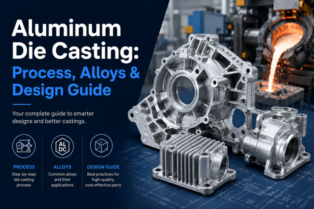
Aluminum die casting is one of the most efficient ways to produce complex, net-shape metal parts at volume. A single die casting can replace multiple machined or fabricated components, deliver consistent geometry across thousands of parts, and achieve surface finishes that require little or no post-processing. For the right application, it's hard to beat on cost, speed, and design freedom.
But die casting isn't the right process for every part — and within die casting, material selection, process parameters, and design choices all have significant impact on part quality, cost, and lead time. This guide covers how aluminum die casting works, which alloys to consider, and how to design parts that take full advantage of the process.
How Aluminum Die Casting Works
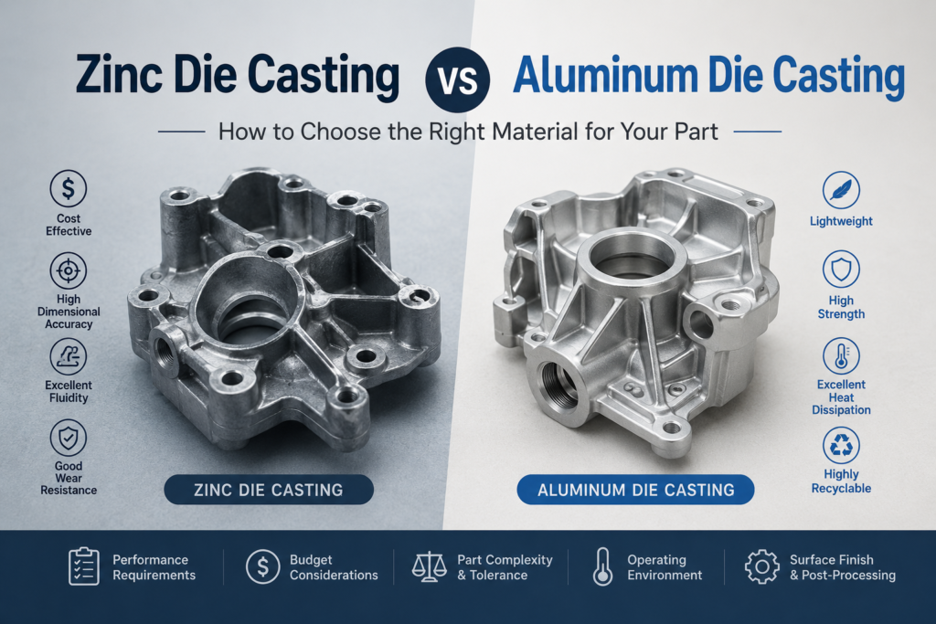
Aluminum die casting is a cold chamber process — meaning the injection system is separate from the molten metal holding furnace. This separation is necessary because aluminum's melting point (~660°C) is too high for the injection components to be submerged in the melt, as they are in hot chamber processes used for zinc.
The cold chamber cycle works as follows. First, molten aluminum alloy is ladled from the holding furnace into the shot sleeve — a cylindrical chamber connected to the die. A hydraulic plunger then drives the metal into the die cavity at high velocity and pressure, typically 700–1,400 bar. The die is water-cooled, so the aluminum solidifies rapidly — cycle times for most parts run 30–120 seconds. Once solidified, the die opens, ejector pins push the part out, and the cycle repeats.
The die itself is machined from H13 tool steel — a hot-work grade chosen for its resistance to thermal fatigue, the primary failure mode in die casting tooling. A well-maintained aluminum die can produce 100,000–150,000 shots before requiring significant rework, depending on part geometry and alloy.
Aluminum Die Casting Alloys
Not all aluminum die casting alloys are interchangeable. Alloy selection affects castability, mechanical properties, corrosion resistance, machinability, and surface treatment compatibility.
For most general-purpose applications — automotive housings, consumer electronics enclosures, industrial equipment brackets — A380 or ADC12 are the default starting points. If your application has specific requirements around corrosion resistance, thin-wall geometry, or structural performance, alloy selection should be part of the early design conversation with your casting supplier.
What Die Casting Can and Can't Do
Strengths of the Process
Limitations to Design Around
Design Guidelines for Aluminum Die Casting
Wall Thickness
Uniform wall thickness is the most important design principle in die casting. Thick sections cool more slowly than thin sections, creating differential shrinkage that causes warpage and internal porosity. Target a consistent wall thickness throughout the part — typically 2–4mm for aluminum — and use ribs to add stiffness rather than increasing wall thickness.
Where wall thickness must vary, transition gradually rather than abruptly. A sudden change from 4mm to 8mm creates a stress concentration and a porosity risk at the transition. A gradual taper over 10–15mm of length manages the transition without these problems.
Draft Angles
Draft angles are tapers on vertical surfaces that allow the part to be ejected from the die without dragging. The minimum draft for aluminum die casting is typically 1° on external surfaces and 2° on internal surfaces (cores). More draft is better — 2–3° on external surfaces gives the die a longer life and improves surface finish on the drafted faces.
Parts with zero-draft walls — surfaces that must be perfectly vertical for functional reasons — can be produced using side-pulls (slides) in the die, but this adds tooling cost and complexity. If a vertical surface is not functionally required, adding draft is almost always the right design decision.
Ribs and Bosses
Ribs add stiffness without adding wall thickness. For die casting, rib thickness should be 60–80% of the adjacent wall thickness to avoid sink marks on the opposite surface. Rib height should not exceed 5 times the rib thickness without careful design attention to fill and ejection. Bosses — raised cylinders for fastener attachment — should have wall thickness consistent with the adjacent wall and be cored where possible to reduce material and improve fill.
Parting Line Placement
The parting line is where the two halves of the die meet — and it defines the geometry that can be produced without slides or cores. Placing the parting line at the largest cross-section of the part minimizes undercuts and simplifies the die. Flash (a thin fin of metal) always forms at the parting line and must be removed in post-processing; placing the parting line on non-cosmetic surfaces minimizes the visual impact of flash removal.
Post-Processing: From Casting to Finished Part
As-cast aluminum parts typically require several post-processing steps before they're ready for use. Deflashing and deburring removes the parting line flash and any rough edges from gate and runner removal. Shot blasting or vibratory finishing improves surface uniformity and removes surface scale. CNC machining adds precision features — bores, threads, sealing surfaces — that require tighter tolerances than casting can achieve. Surface treatment — anodizing, powder coating, e-coating, or painting — provides corrosion protection, aesthetics, or functional surface properties.
The sequence and extent of post-processing depends entirely on the part's requirements. A bracket that will be hidden in an assembly may need only deburring and a coat of paint. A motor housing that interfaces with bearing fits, coolant connections, and mating flanges needs CNC machining of multiple features and potentially a precision anodized finish.