Surface finish is one of the most underspecified requirements on engineering drawings — and one of the most consequential when it's wrong. A sealing face machined to Ra 3.2μm when the application needs Ra 0.8μm will leak. A bearing bore finished to Ra 1.6μm when Ra 0.4μm is required will wear prematurely. A cosmetic surface left to the supplier's default will come back looking different from what the designer imagined.
This guide explains how to specify surface finish correctly on CNC machining drawings: what the parameters mean, how to use the symbols, and which callouts to apply to which features.
A surface-finish requirement should connect the drawing callout to function and a practical inspection method.
The Two Key Surface Finish Parameters: Ra and Rz
Ra — Arithmetic Mean Roughness
Ra is the most widely used surface roughness parameter in engineering drawings. It represents the arithmetic average deviation of the surface profile from its mean line, measured over a defined evaluation length. In simple terms, Ra is the average height of the surface peaks and valleys — a higher Ra means a rougher surface.
Ra is expressed in micrometers (μm) in ISO/metric drawings and microinches (μin) in ASME/imperial drawings. The conversion is 1μm = 39.4μin. Ra 1.6μm is approximately Ra 63μin.
Rz — Mean Roughness Depth
Rz measures the average of the five largest peak-to-valley heights within the evaluation length. It's more sensitive than Ra to occasional large peaks or valleys — which matters for sealing applications (where a single large valley can create a leak path) and tribological applications (where sharp peaks cause accelerated wear).
For most general engineering applications, Ra alone is sufficient. Where occasional extreme peaks or valleys could cause functional failure — sealing faces, precision sliding surfaces — specifying both Ra and Rz provides more complete surface control.
Surface Finish Reference Table for CNC Machined Parts
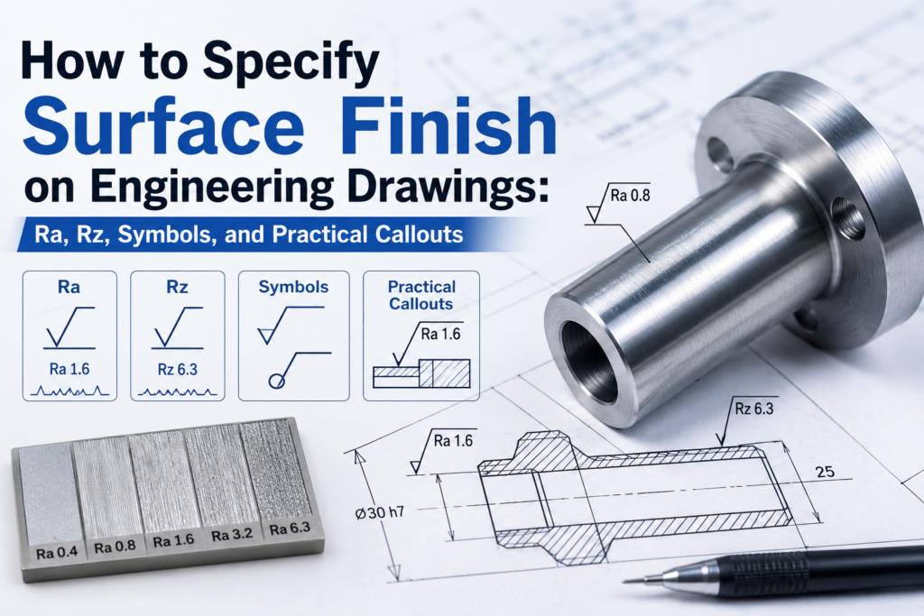
How to Read and Write Surface Finish Symbols
Roughness values and cosmetic appearance are related, but they are not interchangeable acceptance criteria.
The Basic Symbol
The ISO surface finish symbol is a check-mark shape (√) placed on the surface or leader line. The Ra value is written above the horizontal bar of the symbol. A symbol with no Ra value means the surface is to be machined without a specific roughness requirement — the supplier defaults to their standard finish.
Under ASME Y14.36, the symbol is similar but uses a different convention for placement and supplemental requirements. If your drawing follows ASME, confirm which surface texture standard applies — ASME Y14.36M or ISO 1302 — and be consistent throughout the drawing.
Applying Symbols Correctly
Surface finish symbols should be placed on the drawing view where the surface is visible as an edge — not on hidden lines. For surfaces that repeat on the part, a general surface finish note in the title block can set the default: "Unless otherwise specified, all machined surfaces Ra 3.2μm." Individual symbols then override the general note on surfaces with different requirements.
For cylindrical surfaces, the symbol is typically placed on the diameter dimension line or on a leader pointing to the surface. For flat faces, place it directly on the surface edge in the relevant view.
Practical Callout Guidelines by Application
Sealing Surfaces
O-ring grooves, gasket faces, and hydraulic sealing surfaces typically require Ra 0.8–1.6μm. The exact requirement depends on the seal type and operating pressure. Soft elastomeric seals are more forgiving than metal-to-metal seals. Check the seal manufacturer's specification for the required counterface finish — then call it out explicitly on the drawing.
Bearing and Shaft Fits
Bore surfaces that accept rolling element bearings typically require Ra 0.4–0.8μm, with the finer end for precision and high-speed bearings. Shaft journals running in plain bearings need Ra 0.4–0.8μm on the journal surface. These finishes require grinding or fine boring — standard CNC milling won't achieve them consistently.
Sliding and Wear Surfaces
Surfaces in sliding contact — guide rails, piston bores, valve bodies — typically require Ra 0.4–1.6μm depending on speed, load, and lubrication. Very smooth surfaces (Ra <0.2μm) can paradoxically increase friction in boundary lubrication conditions by reducing the ability of the surface to retain a lubricant film. Match your finish specification to the tribological requirements of the application.
Cosmetic and General Machined Surfaces
For surfaces that will be painted, powder coated, or anodized, the as-machined finish is less critical than for functional surfaces — the coating process will modify the surface appearance. Ra 1.6–3.2μm is typically adequate for coated surfaces. For surfaces that remain bare metal and are visible in service, specify your visual acceptance standard separately — a cosmetic appearance requirement is different from a roughness parameter.